Solid elements functions
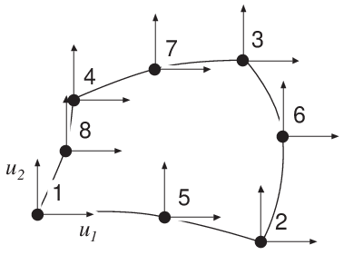
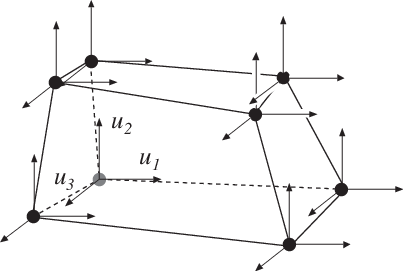
Solid elements are available for two dimensional analysis in plane stress (panels) and plane strain, and for general three dimensional analysis. In the two dimensional case there are a triangular three node element, a quadrilateral four node element, two rectangular four node elements, and quadrilateral isoparametric four and eight node elements. For three dimensional analysis there is an eight node isoparametric element.
The elements are able to deal with both isotropic and anisotropic materials. The triangular element and the three isoparametric elements can also be used together with a nonlinear material model.
The material properties are specified by supplying the constitutive matrix \(\mathbf{D}\) as an input variable to the element functions. This matrix can be formed by the functions described in Section Material functions.
|
|
|
|
|
|
plante |
Compute element matrices for a triangular element |
plants |
Compute stresses and strains |
plantf |
Compute internal element forces |
planqe |
Compute element matrices for a quadrilateral element |
planqs |
Compute stresses and strains |
planre |
Compute element matrices for a rectangular Melosh element |
planrs |
Compute stresses and strains |
plantce |
Compute element matrices for a rectangular Turner-Clough element |
plantcs |
Compute stresses and strains |
plani4e |
Compute element matrices, 4 node isoparametric element |
plani4s |
Compute stresses and strains |
plani4f |
Compute internal element forces |
plani8e |
Compute element matrices, 8 node isoparametric element |
plani8s |
Compute stresses and strains |
plani8f |
Compute internal element forces |
soli8e |
Compute element matrices, 8 node isoparametric element |
soli8s |
Compute stresses and strains |
soli8f |
Compute internal element forces |
plante
- Purpose:
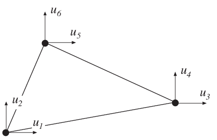
Compute element matrices for a triangular element in plane strain or plane stress.

- Syntax:
Ke = plante(ex, ey, ep, D) [Ke, fe] = plante(ex, ey, ep, D, eq)- Description:
planteprovides an element stiffness matrixKeand an element load vectorfefor a triangular element in plane strain or plane stress.The element nodal coordinates \(x_1, y_1, x_2, \ldots\) are supplied to the function by \(\mathbf{ex}\) and \(\mathbf{ey}\). The type of analysis
ptypeand the element thicknesstare supplied by \(\mathbf{ep}\),\[\begin{split}\begin{array}{l} ptype=1 \quad \text{plane stress} \\ ptype=2 \quad \text{plane strain} \end{array}\end{split}\]and the material properties are supplied by the constitutive matrix
D. Any arbitrary \(\mathbf{D}\)-matrix with dimensions from \(3 \times 3\) to \(6 \times 6\) may be given. For an isotropic elastic material the constitutive matrix can be formed by the functionhooke, see Section Material functions.\[\begin{split}\mathbf{ex} = [\,x_1 \;\; x_2 \;\; x_3\,] \\ \mathbf{ey} = [\,y_1 \;\; y_2 \;\; y_3\,] \\ \mathbf{ep} = [\,ptype \;\; t\,]\end{split}\]\[\begin{split}\mathbf{D} = \begin{bmatrix} D_{11} & D_{12} & D_{13} \\ D_{21} & D_{22} & D_{23} \\ D_{31} & D_{32} & D_{33} \end{bmatrix} \quad \text{or} \quad \mathbf{D} = \begin{bmatrix} D_{11} & D_{12} & D_{13} & D_{14} & [D_{15}] & [D_{16}] \\ D_{21} & D_{22} & D_{23} & D_{24} & [D_{25}] & [D_{26}] \\ D_{31} & D_{32} & D_{33} & D_{34} & [D_{35}] & [D_{36}] \\ D_{41} & D_{42} & D_{43} & D_{44} & [D_{45}] & [D_{46}] \\ [D_{51}] & [D_{52}] & [D_{53}] & [D_{54}] & [D_{55}] & [D_{56}] \\ [D_{61}] & [D_{62}] & [D_{63}] & [D_{64}] & [D_{65}] & [D_{66}] \end{bmatrix}\end{split}\]If uniformly distributed loads are applied to the element, the element load vector
feis computed. The input variable\[\begin{split}\text{eq} = \begin{bmatrix} b_x \\ b_y \end{bmatrix}\end{split}\]containing loads per unit volume, \(b_x\) and \(b_y\), is then given.
- Theory:
The element stiffness matrix \(\mathbf{K}^e\) and the element load vector \(\mathbf{f}_l^e\), stored in
Keandfe, respectively, are computed according to\[\mathbf{K}^e = (\mathbf{C}^{-1})^T \int_A \bar{\mathbf{B}}^T \mathbf{D} \bar{\mathbf{B}}\, t\, dA\, \mathbf{C}^{-1}\]\[\mathbf{f}_l^e = (\mathbf{C}^{-1})^T \int_A \bar{\mathbf{N}}^T \mathbf{b}\, t\, dA\]with the constitutive matrix \(\mathbf{D}\) defined by
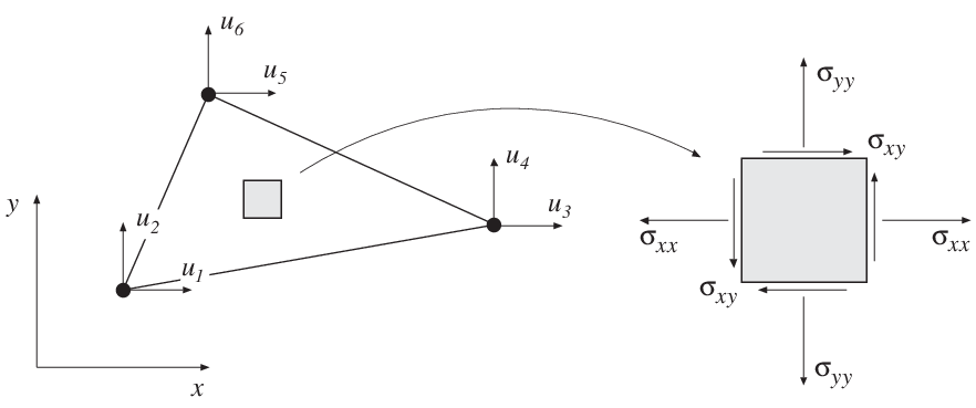
D, and the body force vector \(\mathbf{b}\) defined byeq.The evaluation of the integrals for the triangular element is based on a linear displacement approximation \(\mathbf{u}(x, y)\) and is expressed in terms of the nodal variables \(u_1, u_2, \ldots, u_6\) as
\[\mathbf{u}(x, y) = \mathbf{N}^e \mathbf{a}^e = \bar{\mathbf{N}}\, \mathbf{C}^{-1} \mathbf{a}^e\]where
\[\begin{split}\mathbf{u} = \begin{bmatrix} u_x \\ u_y \end{bmatrix} \quad \bar{\mathbf{N}} = \begin{bmatrix} 1 & x & y & 0 & 0 & 0 \\ 0 & 0 & 0 & 1 & x & y \end{bmatrix}\end{split}\]\[\begin{split}\mathbf{C} = \begin{bmatrix} 1 & x_1 & y_1 & 0 & 0 & 0 \\ 0 & 0 & 0 & 1 & x_1 & y_1 \\ 1 & x_2 & y_2 & 0 & 0 & 0 \\ 0 & 0 & 0 & 1 & x_2 & y_2 \\ 1 & x_3 & y_3 & 0 & 0 & 0 \\ 0 & 0 & 0 & 1 & x_3 & y_3 \\ \end{bmatrix} \quad \mathbf{a}^e = \begin{bmatrix} u_1 \\ u_2 \\ u_3 \\ u_4 \\ u_5 \\ u_6 \end{bmatrix}\end{split}\]The matrix \(\bar{\mathbf{B}}\) is obtained as
\[\begin{split}\bar{\mathbf{B}} = \tilde{\nabla} \bar{\mathbf{N}} \quad \text{where} \quad \tilde{\nabla} = \begin{bmatrix} \dfrac{\partial}{\partial x} & 0 \\ 0 & \dfrac{\partial}{\partial y} \\ \dfrac{\partial}{\partial y} & \dfrac{\partial}{\partial x} \end{bmatrix}\end{split}\]If a larger \(\mathbf{D}\)-matrix than \(3 \times 3\) is used for plane stress (\(ptype=1\)), the \(\mathbf{D}\)-matrix is reduced to a \(3 \times 3\) matrix by static condensation using \(\sigma_{zz} = \sigma_{xz} = \sigma_{yz} = 0\). These stress components are connected with the rows 3, 5 and 6 in the D-matrix respectively.
If a larger \(\mathbf{D}\)-matrix than \(3 \times 3\) is used for plane strain (\(ptype=2\)), the \(\mathbf{D}\)-matrix is reduced to a \(3 \times 3\) matrix using \(\varepsilon_{zz} = \gamma_{xz} = \gamma_{yz} = 0\). This implies that a \(3 \times 3\) \(\mathbf{D}\)-matrix is created by the rows and the columns 1, 2 and 4 from the original D-matrix.
Evaluation of the integrals for the triangular element yields
\[\mathbf{K}^e = (\mathbf{C}^{-1})^T \bar{\mathbf{B}}^T \mathbf{D} \bar{\mathbf{B}}\, \mathbf{C}^{-1}\, t\, A\]\[\mathbf{f}_l^e = \frac{A t}{3} \begin{bmatrix} b_x & b_y & b_x & b_y & b_x & b_y \end{bmatrix}^T\]where the element area \(A\) is determined as
\[\begin{split}A = \frac{1}{2} \det \begin{bmatrix} 1 & x_1 & y_1 \\ 1 & x_2 & y_2 \\ 1 & x_3 & y_3 \end{bmatrix}\end{split}\]
plants
- Purpose:
Compute stresses and strains in a triangular element in plane strain or plane stress.
- Syntax:
[es, et] = plants(ex, ey, ep, D, ed)- Description:
plantscomputes the stressesesand the strainsetin a triangular element in plane strain or plane stress.The input variables \(\mathbf{ex}\), \(\mathbf{ey}\), \(\mathbf{ep}\) and \(\mathbf{D}\) are defined in
plante. The vector \(\mathbf{ed}\) contains the nodal displacements \(\mathbf{a}^e\) of the element and is obtained by the functionextractas\[\mathbf{ed} = (\mathbf{a}^e)^T = [\, u_1\;\; u_2\;\; \dots \;\; u_6\,]\]The output variables
\[\mathrm{es} = \boldsymbol{\sigma}^T = \left[\, \sigma_{xx}\; \sigma_{yy}\; [\sigma_{zz}]\; \sigma_{xy}\; [\sigma_{xz}]\; [\sigma_{yz}]\, \right]\]\[\mathrm{et} = \boldsymbol{\varepsilon}^T = [\, \varepsilon_{xx}\; \varepsilon_{yy}\; [\varepsilon_{zz}]\; \gamma_{xy}\; [\gamma_{xz}]\; [\gamma_{yz}]\,]\]contain the stress and strain components. The size of
esandetfollows the size ofD. Note that for plane stress \(\varepsilon_{zz} \neq 0\), and for plane strain \(\sigma_{zz} \neq 0\).- Theory:
The strains and stresses are computed according to
\[\boldsymbol{\varepsilon} = \bar{\mathbf{B}}\, \mathbf{C}^{-1}\, \mathbf{a}^e\]\[\boldsymbol{\sigma} = \mathbf{D}\, \boldsymbol{\varepsilon}\]where the matrices \(\mathbf{D}\), \(\bar{\mathbf{B}}\), \(\mathbf{C}\) and \(\mathbf{a}^e\) are described in
plante. Note that both the strains and the stresses are constant in the element.
plantf
- Purpose:
Compute internal element force vector in a triangular element in plane strain or plane stress.
- Syntax:
ef = plantf(ex, ey, ep, es)- Description:
plantfcomputes the internal element forcesefin a triangular element in plane strain or plane stress.The input variables \(\mathbf{ex}\), \(\mathbf{ey}\) and \(\mathbf{ep}\) are defined in
plante, and the input variable \(\mathbf{es}\) is defined inplants.The output variable
\[\mathrm{ef} = \mathbf{f}_i^{eT} = \left[\, f_{i1}\; f_{i2}\; \dots \; f_{i6}\; \right]\]contains the components of the internal force vector.
- Theory:
The internal force vector is computed according to
\[\mathbf{f}_i^e = (\mathbf{C}^{-1})^T \int_A \bar{\mathbf{B}}^T \boldsymbol{\sigma}\; t\; dA\]where the matrices \(\bar{\mathbf{B}}\) and \(\mathbf{C}\) are defined in
planteand \(\boldsymbol{\sigma}\) is defined inplants.Evaluation of the integral for the triangular element yields
\[\mathbf{f}_i^e = (\mathbf{C}^{-1})^T \bar{\mathbf{B}}^T\,\boldsymbol{\sigma}\; t\; A\]
planqe
- Purpose:
Compute element matrices for a quadrilateral element in plane strain or plane stress.

- Syntax:
Ke = planqe(ex, ey, ep, D) [Ke, fe] = planqe(ex, ey, ep, D, eq)- Description:
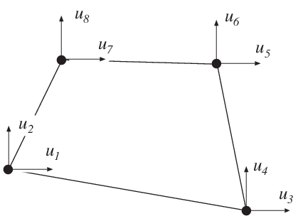
planqeprovides an element stiffness matrix \(Ke\) and an element load vector \(fe\) for a quadrilateral element in plane strain or plane stress.The element nodal coordinates \(x_1\), \(y_1\), \(x_2\), etc. are supplied to the function by \(\mathbf{ex}\) and \(\mathbf{ey}\). The type of analysis \(ptype\) and the element thickness \(t\) are supplied by \(\mathbf{ep}\):
\[\begin{split}\begin{array}{lll} ptype=1 & \quad \text{plane stress} \\ ptype=2 & \quad \text{plane strain} \end{array}\end{split}\]The material properties are supplied by the constitutive matrix \(D\). Any arbitrary \(\mathbf{D}\)-matrix with dimensions from \(3 \times 3\) to \(6 \times 6\) may be given. For an isotropic elastic material the constitutive matrix can be formed by the function
hooke, see Section Material functions.\[\begin{split}\mathbf{ex} = [\,x_1 \;\, x_2 \;\; x_3\;\, x_4\,] \\ \mathbf{ey} = [\,y_1 \;\,\, y_2 \;\; y_3\;\,\, y_4\,] \\ \mathbf{ep} = [\,ptype \;\, t\,]\end{split}\]\[\begin{split}\mathbf{D} = \begin{bmatrix} D_{11} & D_{12} & D_{13} \\ D_{21} & D_{22} & D_{23} \\ D_{31} & D_{32} & D_{33} \end{bmatrix} \quad \text{or} \quad \mathbf{D} = \begin{bmatrix} D_{11} & D_{12} & D_{13} & D_{14} & D_{15} & D_{16} \\ D_{21} & D_{22} & D_{23} & D_{24} & D_{25} & D_{26} \\ D_{31} & D_{32} & D_{33} & D_{34} & D_{35} & D_{36} \\ D_{41} & D_{42} & D_{43} & D_{44} & D_{45} & D_{46} \\ D_{51} & D_{52} & D_{53} & D_{54} & D_{55} & D_{56} \\ D_{61} & D_{62} & D_{63} & D_{64} & D_{65} & D_{66} \end{bmatrix}\end{split}\]If uniformly distributed loads are applied on the element, the element load vector \(fe\) is computed. The input variable
\[\begin{split}eq = \begin{bmatrix} b_x \\ b_y \end{bmatrix}\end{split}\]contains loads per unit volume, \(b_x\) and \(b_y\).
- Theory:
In computing the element matrices, two more degrees of freedom are introduced. The location of these two degrees of freedom is defined by the mean value of the coordinates at the corner points. Four sets of element matrices are calculated using
plante. These matrices are then assembled and the two extra degrees of freedom are eliminated by static condensation.
planqs
- Purpose:
Compute stresses and strains in a quadrilateral element in plane strain or plane stress.

- Syntax:
[es,et]=planqs(ex,ey,ep,D,ed) [es,et]=planqs(ex,ey,ep,D,ed,eq)- Description:
planqscomputes the stressesesand the strainsetin a quadrilateral element in plane strain or plane stress.The input variables \(\mathbf{ex}\), \(\mathbf{ey}\), \(\mathbf{ep}\), \(\mathbf{D}\) and \(\mathbf{eq}\) are defined in
planqe. The vector \(\mathbf{ed}\) contains the nodal displacements \(\mathbf{a}^e\) of the element and is obtained by the functionextractas\[\mathbf{ed} = (\mathbf{a}^e)^T = [\,u_1\;\; u_2\;\; \dots \;\; u_8\,]\]If body forces are applied to the element the variable \(\mathbf{eq}\) must be included.
The output variables
\[\mathrm{es} = \boldsymbol{\sigma}^T = [\, \sigma_{xx}\; \sigma_{yy}\; [\sigma_{zz}]\; \sigma_{xy}\; [\sigma_{xz}]\; [\sigma_{yz}]\,]\]\[\mathrm{et} = \boldsymbol{\varepsilon}^T = [\,\varepsilon_{xx}\;\varepsilon_{yy}\;[\varepsilon_{zz}]\;\gamma_{xy}\;[\gamma_{xz}]\;[\gamma_{yz}]\,]\]contain the stress and strain components. The size of
esandetfollows the size ofD. Note that for plane stress \(\varepsilon_{zz} \neq 0\), and for plane strain \(\sigma_{zz} \neq 0\).- Theory:
By assembling triangular elements as described in
planqea system of equations containing 10 degrees of freedom is obtained. From this system of equations the two unknown displacements at the center of the element are computed. Then according to the description inplantsthe strain and stress components in each of the four triangular elements are produced. Finally the quadrilateral element strains and stresses are computed as area weighted mean values from the values of the four triangular elements. If uniformly distributed loads are applied on the element, the element load vectoreqis needed for the calculations.
planre
- Purpose:
Compute element matrices for a rectangular (Melosh) element in plane strain or plane stress.

- Syntax:
Ke = planre(ex, ey, ep, D) [Ke, fe] = planre(ex, ey, ep, D, eq)- Description:
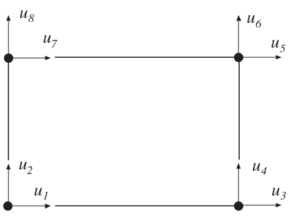
planre provides an element stiffness matrix Ke and an element load vector fe for a rectangular (Melosh) element in plane strain or plane stress. This element can only be used if the element edges are parallel to the coordinate axis.
The element nodal coordinates \((x_1, y_1)\) and \((x_3, y_3)\) are supplied to the function by ex and ey. The type of analysis ptype and the element thickness t are supplied by ep,
\[\begin{split}\begin{array}{lll} ptype=1 \quad \mbox{plane stress} \\ ptype=2 \quad \mbox{plane strain} \end{array}\end{split}\]and the material properties are supplied by the constitutive matrix D. Any arbitrary D-matrix with dimensions from \(3 \times 3\) to \(6 \times 6\) may be given. For an isotropic elastic material the constitutive matrix can be formed by the function hooke, see Section Material.
\[\begin{split}\begin{array}{l} \mathbf{ex} = [\,x_1 \;\, x_3\,] \\ \mathbf{ey} = [\,y_1 \;\, y_3\,] \end{array} \qquad \mathbf{ep} = [\,ptype \;\, t\,]\end{split}\]\[\begin{split}\mathbf{D} = \begin{bmatrix} D_{11} & D_{12} & D_{13} \\ D_{21} & D_{22} & D_{23} \\ D_{31} & D_{32} & D_{33} \end{bmatrix} \quad \text{or} \quad \mathbf{D} = \begin{bmatrix} D_{11} & D_{12} & D_{13} & D_{14} & [D_{15}] & [D_{16}] \\ D_{21} & D_{22} & D_{23} & D_{24} & [D_{25}] & [D_{26}] \\ D_{31} & D_{32} & D_{33} & D_{34} & [D_{35}] & [D_{36}] \\ D_{41} & D_{42} & D_{43} & D_{44} & [D_{45}] & [D_{46}] \\ [D_{51}] & [D_{52}] & [D_{53}] & [D_{54}] & [D_{55}] & [D_{56}] \\ [D_{61}] & [D_{62}] & [D_{63}] & [D_{64}] & [D_{65}] & [D_{66}] \end{bmatrix}\end{split}\]If uniformly distributed loads are applied on the element, the element load vector fe is computed. The input variable
\[\begin{split}eq = \begin{bmatrix} b_x \\ b_y \end{bmatrix}\end{split}\]containing loads per unit volume, \(b_x\) and \(b_y\), is then given.
- Theory:
The element stiffness matrix \(\mathbf{K}^e\) and the element load vector \(\mathbf{f}_l^e\), stored in Ke and fe, respectively, are computed according to
\[\mathbf{K}^e = \int_A \mathbf{B}^{eT} \mathbf{D} \mathbf{B}^e t\, dA\]\[\mathbf{f}_l^e = \int_A \mathbf{N}^{eT} \mathbf{b} t\, dA\]with the constitutive matrix \(\mathbf{D}\) defined by D, and the body force vector \(\mathbf{b}\) defined by eq.
The evaluation of the integrals for the rectangular element is based on a bilinear displacement approximation \(\mathbf{u}(x,y)\) and is expressed in terms of the nodal variables \(u_1, u_2, \dots, u_8\) as
\[\mathbf{u}(x, y) = \mathbf{N}^e \mathbf{a}^e\]where
\[\begin{split}\mathbf{u} = \begin{bmatrix} u_x \\ u_y \end{bmatrix} \quad \mathbf{N}^e = \begin{bmatrix} N^e_1 & 0 & N^e_2 & 0 & N^e_3 & 0 & N^e_4 & 0 \\ 0 & N^e_1 & 0 & N^e_2 & 0 & N^e_3 & 0 & N^e_4 \end{bmatrix} \quad \mathbf{a}^e = \begin{bmatrix} u_1 \\ u_2 \\ \vdots \\ u_8 \end{bmatrix}\end{split}\]With a local coordinate system located at the center of the element, the element shape functions \(N^e_1\)–\(N^e_4\) are obtained as
\[\begin{split}N^e_1 = \frac{1}{4ab}(x - x_2)(y - y_4) \\ N^e_2 = -\frac{1}{4ab}(x - x_1)(y - y_3) \\ N^e_3 = \frac{1}{4ab}(x - x_4)(y - y_2) \\ N^e_4 = -\frac{1}{4ab}(x - x_3)(y - y_1)\end{split}\]where
\[a = \frac{1}{2}(x_3 - x_1) \quad \text{and} \quad b = \frac{1}{2}(y_3 - y_1)\]The matrix \(\mathbf{B}^e\) is obtained as
\[\begin{split}\mathbf{B}^e = \tilde{\nabla} \mathbf{N}^e \qquad \text{where} \quad \tilde{\nabla} = \begin{bmatrix} \dfrac{\partial}{\partial x} & 0 \\ 0 & \dfrac{\partial}{\partial y} \\ \dfrac{\partial}{\partial y} & \dfrac{\partial}{\partial x} \end{bmatrix}\end{split}\]If a larger D-matrix than \(3 \\times 3\) is used for plane stress (\(ptype=1\)), the D-matrix is reduced to a \(3 \\times 3\) matrix by static condensation using \(\sigma_{zz} = \sigma_{xz} = \sigma_{yz} = 0\). These stress components are connected with the rows 3, 5 and 6 in the D-matrix respectively.
If a larger D-matrix than \(3 \\times 3\) is used for plane strain (\(ptype=2\)), the D-matrix is reduced to a \(3 \\times 3\) matrix using \(\varepsilon_{zz} = \gamma_{xz} = \gamma_{yz} = 0\). This implies that a \(3 \\times 3\) D-matrix is created by the rows and the columns 1, 2 and 4 from the original D-matrix.
Evaluation of the integrals for the rectangular element can be done either analytically or numerically by use of a \(2 \\times 2\) point Gauss integration. The element load vector \(\mathbf{f}_l^e\) yields
\[\begin{split}\mathbf{f}_l^e = abt \begin{bmatrix} b_x \\ b_y \\ b_x \\ b_y \\ b_x \\ b_y \\ b_x \\ b_y \end{bmatrix}\end{split}\]
planrs
- Purpose:
Compute stresses and strains in a rectangular (Melosh) element in plane strain or plane stress.

- Syntax:
[es,et]=planrs(ex,ey,ep,D,ed)- Description:
planrscomputes the stressesesand the strainsetin a rectangular (Melosh) element in plane strain or plane stress. The stress and strain components are computed at the center of the element.The input variables \(\mathbf{ex}\), \(\mathbf{ey}\), \(\mathbf{ep}\) and \(\mathbf{D}\) are defined in
planre. The vector \(\mathbf{ed}\) contains the nodal displacements \(\mathbf{a}^e\) of the element and is obtained by the functionextractas\[\mathbf{ed} = (\mathbf{a}^e)^T = [\,u_1\;\; u_2\;\; \dots \;\; u_8\,]\]The output variables
\[\mathrm{es} = \boldsymbol{\sigma}^T = [\, \sigma_{xx}\; \sigma_{yy}\; [\sigma_{zz}]\; \sigma_{xy}\; [\sigma_{xz}]\; [\sigma_{yz}]\,]\]\[\mathrm{et} = \boldsymbol{\varepsilon}^T = [\, \varepsilon_{xx}\; \varepsilon_{yy}\; [\varepsilon_{zz}]\; \gamma_{xy}\; [\gamma_{xz}]\; [\gamma_{yz}]\,]\]contain the stress and strain components. The size of
esandetfollows the size ofD. Note that for plane stress \(\varepsilon_{zz} \neq 0\), and for plane strain \(\sigma_{zz} \neq 0\).- Theory:
The strains and stresses are computed according to
\[\boldsymbol{\varepsilon} = \mathbf{B}^e\,\mathbf{a}^e\]\[\boldsymbol{\sigma} = \mathbf{D}\,\boldsymbol{\varepsilon}\]where the matrices \(\mathbf{D}\), \(\mathbf{B}^e\), and \(\mathbf{a}^e\) are described in
planre, and where the evaluation point \((x, y)\) is chosen to be at the center of the element.
plantce
- Purpose:
Compute element matrices for a rectangular (Turner-Clough) element in plane strain or plane stress.
- Syntax:
Ke = plantce(ex, ey, ep) [Ke, fe] = plantce(ex, ey, ep, eq)- Description:
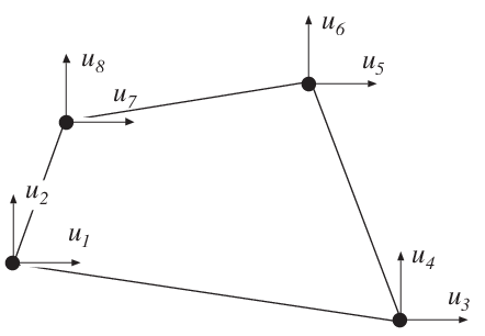
plantceprovides an element stiffness matrixKeand an element load vectorfefor a rectangular (Turner-Clough) element in plane strain or plane stress. This element can only be used if the material is isotropic and if the element edges are parallel to the coordinate axis.The element nodal coordinates \((x_1, y_1)\) and \((x_3, y_3)\) are supplied to the function by \(\mathbf{ex}\) and \(\mathbf{ey}\). The state of stress
ptype, the element thickness \(t\) and the material properties \(E\) and \(\nu\) are supplied by \(\mathbf{ep}\). For plane stress \(ptype=1\) and for plane strain \(ptype=2\).\[\begin{split}\begin{array}{l} \mathbf{ex} = [\, x_1 \;\; x_3\,] \\ \mathbf{ey} = [\, y_1 \;\; y_3\,] \end{array} \qquad \mathbf{ep} = [\, ptype \;\; t \;\; E \;\; \nu \,]\end{split}\]If uniformly distributed loads are applied to the element, the element load vector
feis computed. The input variable\[\begin{split}eq = \begin{bmatrix} b_x \\ b_y \end{bmatrix}\end{split}\]containing loads per unit volume, \(b_x\) and \(b_y\), is then given.
- Theory:
The element stiffness matrix \(\mathbf{K}^e\) and the element load vector \(\mathbf{f}_l^e\), stored in
Keandfe, respectively, are computed according to\[\mathbf{K}^e = \int_A \mathbf{B}^{eT} \mathbf{D} \mathbf{B}^e t\, dA\]\[\mathbf{f}_l^e = \int_A \mathbf{N}^{eT} \mathbf{b} t\, dA\]where the constitutive matrix \(\mathbf{D}\) is described in
hooke, see Section Material functions, and the body force vector \(\mathbf{b}\) is defined byeq.The evaluation of the integrals for the Turner-Clough element is based on a displacement field \(\mathbf{u}(x, y)\) built up of a bilinear displacement approximation superposed by bubble functions in order to create a linear stress field over the element. The displacement field is expressed in terms of the nodal variables \(u_1, u_2, \dots, u_8\) as
\[\mathbf{u}(x, y) = \mathbf{N}^e \mathbf{a}^e\]where
\[\begin{split}\mathbf{u} = \begin{bmatrix} u_x \\ u_y \end{bmatrix} \quad \mathbf{N}^e = \begin{bmatrix} N^e_1 & N^e_5 & N^e_2 & -N^e_5 & N^e_3 & N^e_5 & N^e_4 & -N^e_5 \\ N^e_6 & N^e_1 & -N^e_6 & N^e_2 & N^e_6 & N^e_3 & -N^e_6 & N^e_4 \end{bmatrix} \quad \mathbf{a}^e = \begin{bmatrix} u_1 \\ u_2 \\ \vdots \\ u_8 \end{bmatrix}\end{split}\]With a local coordinate system located at the center of the element, the element shape functions \(N^e_1\)–\(N^e_6\) are obtained as
\[\begin{split}N^e_1 = \frac{1}{4ab}(a-x)(b-y) \\ N^e_2 = \frac{1}{4ab}(a+x)(b-y) \\ N^e_3 = \frac{1}{4ab}(a+x)(b+y) \\ N^e_4 = \frac{1}{4ab}(a-x)(b+y) \\ N^e_5 = \frac{1}{8ab}\left[ (b^2-y^2) + \nu (a^2-x^2) \right] \\ N^e_6 = \frac{1}{8ab}\left[ (a^2-x^2) + \nu (b^2-y^2) \right]\end{split}\]where
\[a = \frac{1}{2}(x_3 - x_1) \qquad b = \frac{1}{2}(y_3 - y_1)\]The matrix \(\mathbf{B}^e\) is obtained as
\[\begin{split}\mathbf{B}^e = \tilde{\nabla} \mathbf{N}^e \qquad \text{where} \quad \tilde{\nabla} = \begin{bmatrix} \dfrac{\partial}{\partial x} & 0 \\ 0 & \dfrac{\partial}{\partial y} \\ \dfrac{\partial}{\partial y} & \dfrac{\partial}{\partial x} \end{bmatrix}\end{split}\]Evaluation of the integrals for the Turner-Clough element can be done either analytically or numerically by use of a \(2 \times 2\) point Gauss integration. The element load vector \(\mathbf{f}_l^e\) yields
\[\begin{split}\mathbf{f}_l^e = abt \begin{bmatrix} b_x \\ b_y \\ b_x \\ b_y \\ b_x \\ b_y \\ b_x \\ b_y \end{bmatrix}\end{split}\]
plantcs
- Purpose:
Compute stresses and strains in a Turner-Clough element in plane strain or plane stress.
- Syntax:
[es, et] = plantcs(ex, ey, ep, ed)- Description:
plantcscomputes the stressesesand the strainsetin a rectangular Turner-Clough element in plane strain or plane stress. The stress and strain components are computed at the center of the element.The input variables \(\mathbf{ex}\), \(\mathbf{ey}\), and \(\mathbf{ep}\) are defined in
plantce. The vector \(\mathbf{ed}\) contains the nodal displacements \(\mathbf{a}^e\) of the element and is obtained by the functionextractas\[\mathbf{ed} = (\mathbf{a}^e)^T = [\, u_1\;\; u_2\;\; \dots \;\; u_8\,]\]The output variables
\[\mathrm{es} = \boldsymbol{\sigma}^T = [\, \sigma_{xx}\; \sigma_{yy}\; [\sigma_{zz}]\; \sigma_{xy}\; [\sigma_{xz}]\; [\sigma_{yz}]\,]\]\[\mathrm{et} = \boldsymbol{\varepsilon}^T = [\, \varepsilon_{xx}\; \varepsilon_{yy}\; [\varepsilon_{zz}]\; \gamma_{xy}\; [\gamma_{xz}]\; [\gamma_{yz}]\,]\]contain the stress and strain components. The size of
esandetfollows the size ofD. Note that for plane stress \(\varepsilon_{zz} \neq 0\), and for plane strain \(\sigma_{zz} \neq 0\).- Theory:
The strains and stresses are computed according to
\[\boldsymbol{\varepsilon} = \mathbf{B}^e\,\mathbf{a}^e\]\[\boldsymbol{\sigma} = \mathbf{D}\;\boldsymbol{\varepsilon}\]where the matrices \(\mathbf{D}\), \(\mathbf{B}^e\), and \(\mathbf{a}^e\) are described in
plantce, and where the evaluation point \((x, y)\) is chosen to be at the center of the element.
plani4e
- Purpose:
Compute element matrices for a 4 node isoparametric element in plane strain or plane stress.
- Syntax:
Ke = plani4e(ex, ey, ep, D) [Ke, fe] = plani4e(ex, ey, ep, D, eq)- Description:
plani4eprovides an element stiffness matrixKeand an element load vectorfefor a 4 node isoparametric element in plane strain or plane stress.The element nodal coordinates \(x_1, y_1, x_2, \ldots\) are supplied to the function by \(\mathbf{ex}\) and \(\mathbf{ey}\). The type of analysis \(ptype\), the element thickness \(t\), and the number of Gauss points \(n\) are supplied by \(\mathbf{ep}\):
\[\begin{split}\begin{array}{lll} ptype=1 & \text{plane stress} & (n \times n) \text{ integration points} \\ ptype=2 & \text{plane strain} & n=1,2,3 \end{array}\end{split}\]The material properties are supplied by the constitutive matrix \(D\). Any arbitrary \(\mathbf{D}\)-matrix with dimensions from \(3 \times 3\) to \(6 \times 6\) may be given. For an isotropic elastic material the constitutive matrix can be formed by the function
hooke, see Section Material functions.\[\begin{split}\mathbf{ex} = [\,x_1 \;\, x_2 \;\; x_3\;\, x_4\,] \\ \mathbf{ey} = [\,y_1 \;\,\, y_2 \;\; y_3\;\,\, y_4\,] \\ \mathbf{ep} = [\,ptype \;\, t\;\, n\,]\end{split}\]\[\begin{split}\mathbf{D} = \begin{bmatrix} D_{11} & D_{12} & D_{13} \\ D_{21} & D_{22} & D_{23} \\ D_{31} & D_{32} & D_{33} \end{bmatrix} \quad \text{or} \quad \mathbf{D} = \begin{bmatrix} D_{11} & D_{12} & D_{13} & D_{14} & [D_{15}] & [D_{16}] \\ D_{21} & D_{22} & D_{23} & D_{24} & [D_{25}] & [D_{26}] \\ D_{31} & D_{32} & D_{33} & D_{34} & [D_{35}] & [D_{36}] \\ D_{41} & D_{42} & D_{43} & D_{44} & [D_{45}] & [D_{46}] \\ [D_{51}] & [D_{52}] & [D_{53}] & [D_{54}] & [D_{55}] & [D_{56}] \\ [D_{61}] & [D_{62}] & [D_{63}] & [D_{64}] & [D_{65}] & [D_{66}] \end{bmatrix}\end{split}\]If different \(\mathbf{D}_i\) matrices are used in the Gauss points, these \(\mathbf{D}_i\) matrices are stored in a global vector
D. For numbering of the Gauss points, seeeciinplani4s.\[\begin{split}\mathbf{D} = \begin{bmatrix} \mathbf{D}_1 \\ \mathbf{D}_2 \\ \vdots \\ \mathbf{D}_{n^2} \end{bmatrix}\end{split}\]If uniformly distributed loads are applied to the element, the element load vector
feis computed. The input variable\[\begin{split}\mathrm{eq} = \begin{bmatrix} b_x \\ b_y \end{bmatrix}\end{split}\]containing loads per unit volume, \(b_x\) and \(b_y\), is then given.
- Theory:
The element stiffness matrix \(\mathbf{K}^e\) and the element load vector \(\mathbf{f}_l^e\), stored in
Keandfe, respectively, are computed according to\[\begin{split}\mathbf{K}^e = \int_A \mathbf{B}^{eT} \mathbf{D} \mathbf{B}^e t\, dA \\ \mathbf{f}_l^e = \int_A \mathbf{N}^{eT} \mathbf{b} t\, dA\end{split}\]with the constitutive matrix \(\mathbf{D}\) defined by
D, and the body force vector \(\mathbf{b}\) defined byeq.The evaluation of the integrals for the isoparametric 4 node element is based on a displacement approximation \(\mathbf{u}(\xi, \eta)\), expressed in a local coordinate system in terms of the nodal variables \(u_1, u_2, \ldots, u_8\) as
\[\mathbf{u}(\xi, \eta) = \mathbf{N}^e \mathbf{a}^e\]where
\[\begin{split}\mathbf{u} = \begin{bmatrix} u_x \\ u_y \end{bmatrix} \qquad \mathbf{N}^e = \begin{bmatrix} N_1^e & 0 & N_2^e & 0 & N_3^e & 0 & N_4^e & 0 \\ 0 & N_1^e & 0 & N_2^e & 0 & N_3^e & 0 & N_4^e \end{bmatrix} \qquad \mathbf{a}^e = \begin{bmatrix} u_1 \\ u_2 \\ \vdots \\ u_8 \end{bmatrix}\end{split}\]The element shape functions are given by
\[\begin{split}N_1^e = \frac{1}{4}(1-\xi)(1-\eta) \qquad N_2^e = \frac{1}{4}(1+\xi)(1-\eta) \\ N_3^e = \frac{1}{4}(1+\xi)(1+\eta) \qquad N_4^e = \frac{1}{4}(1-\xi)(1+\eta)\end{split}\]The matrix \(\mathbf{B}^e\) is obtained as
\[\begin{split}\mathbf{B}^e = \tilde{\nabla} \mathbf{N}^e \qquad \text{where} \quad \tilde{\nabla} = \begin{bmatrix} \frac{\partial}{\partial x} & 0 \\ 0 & \frac{\partial}{\partial y} \\ \frac{\partial}{\partial y} & \frac{\partial}{\partial x} \end{bmatrix}\end{split}\]and
\[\begin{split}\begin{bmatrix} \frac{\partial}{\partial x} \\ \frac{\partial}{\partial y} \end{bmatrix} = (\mathbf{J}^T)^{-1} \begin{bmatrix} \frac{\partial}{\partial \xi} \\ \frac{\partial}{\partial \eta} \end{bmatrix} \qquad \mathbf{J} = \begin{bmatrix} \frac{\partial x}{\partial \xi} & \frac{\partial x}{\partial \eta} \\ \frac{\partial y}{\partial \xi} & \frac{\partial y}{\partial \eta} \end{bmatrix}\end{split}\]If a larger \(\mathbf{D}\)-matrix than \(3 \times 3\) is used for plane stress (\(ptype=1\)), the \(\mathbf{D}\)-matrix is reduced to a \(3 \times 3\) matrix by static condensation using \(\sigma_{zz} = \sigma_{xz} = \sigma_{yz} = 0\). These stress components are connected with the rows 3, 5 and 6 in the D-matrix respectively.
If a larger \(\mathbf{D}\)-matrix than \(3 \times 3\) is used for plane strain (\(ptype=2\)), the \(\mathbf{D}\)-matrix is reduced to a \(3 \times 3\) matrix using \(\varepsilon_{zz} = \gamma_{xz} = \gamma_{yz} = 0\). This implies that a \(3 \times 3\) \(\mathbf{D}\)-matrix is created by the rows and the columns 1, 2 and 4 from the original D-matrix.
Evaluation of the integrals is done by Gauss integration.
plani4s
- Purpose:
Compute stresses and strains in a 4 node isoparametric element in plane strain or plane stress.
- Syntax:
[es,et,eci]=plani4s(ex,ey,ep,D,ed)- Description:
plani4scomputes stressesesand the strainsetin a 4 node isoparametric element in plane strain or plane stress.The input variables \(\mathbf{ex}\), \(\mathbf{ey}\), \(\mathbf{ep}\) and the matrix \(\mathbf{D}\) are defined in
plani4e. The vector \(\mathbf{ed}\) contains the nodal displacements \(\mathbf{a}^e\) of the element and is obtained by the functionextractas\[\mathbf{ed} = (\mathbf{a}^e)^T = [\,u_1\;\; u_2\;\; \dots \;\; u_8\,]\]The output variables
\[\begin{split}\mathrm{es} = \boldsymbol{\sigma}^T = \begin{bmatrix} \sigma^1_{xx} & \sigma^1_{yy} & [\sigma^1_{zz}] & \sigma^1_{xy} & [\sigma^1_{xz}] & [\sigma^1_{yz}] \\ \sigma^2_{xx} & \sigma^2_{yy} & [\sigma^2_{zz}] & \sigma^2_{xy} & [\sigma^2_{xz}] & [\sigma^2_{yz}] \\ \vdots & \vdots & \vdots & \vdots & \vdots & \vdots \\ \sigma^{n^2}_{xx} & \sigma^{n^2}_{yy} & [\sigma^{n^2}_{zz}] & \sigma^{n^2}_{xy} & [\sigma^{n^2}_{xz}] & [\sigma^{n^2}_{yz}] \end{bmatrix}\end{split}\]\[\begin{split}\mathrm{et} = \boldsymbol{\varepsilon}^T = \begin{bmatrix} \varepsilon^1_{xx} & \varepsilon^1_{yy} & [\varepsilon^1_{zz}] & \gamma^1_{xy} & [\gamma^1_{xz}] & [\gamma^1_{yz}] \\ \varepsilon^2_{xx} & \varepsilon^2_{yy} & [\varepsilon^2_{zz}] & \gamma^2_{xy} & [\gamma^2_{xz}] & [\gamma^2_{yz}] \\ \vdots & \vdots & \vdots & \vdots & \vdots & \vdots \\ \varepsilon^{n^2}_{xx} & \varepsilon^{n^2}_{yy} & [\varepsilon^{n^2}_{zz}] & \gamma^{n^2}_{xy} & [\gamma^{n^2}_{xz}] & [\gamma^{n^2}_{yz}] \end{bmatrix}\end{split}\]\[\begin{split}\mathbf{eci} = \begin{bmatrix} x_1 & y_1 \\ x_2 & y_2 \\ \vdots & \vdots \\ x_{n^2} & y_{n^2} \end{bmatrix}\end{split}\]contain the stress and strain components, and the coordinates of the integration points. The index \(n\) denotes the number of integration points used within the element, cf.
plani4e. The number of columns inesandetfollows the size ofD. Note that for plane stress \(\varepsilon_{zz} \neq 0\), and for plane strain \(\sigma_{zz} \neq 0\).- Theory:
The strains and stresses are computed according to
\[\boldsymbol{\varepsilon} = \mathbf{B}^e\,\mathbf{a}^e\]\[\boldsymbol{\sigma} = \mathbf{D}\;\boldsymbol{\varepsilon}\]where the matrices \(\mathbf{D}\), \(\mathbf{B}^e\), and \(\mathbf{a}^e\) are described in
plani4e, and where the integration points are chosen as evaluation points.
plani4f
- Purpose:
Compute internal element force vector in a 4 node isoparametric element in plane strain or plane stress.
- Syntax:
ef = plani4f(ex, ey, ep, es)- Description:
plani4fcomputes the internal element forces \(\mathrm{ef}\) in a 4 node isoparametric element in plane strain or plane stress.The input variables \(\mathbf{ex}\), \(\mathbf{ey}\) and \(\mathbf{ep}\) are defined in
plani4e, and the input variable \(\mathbf{es}\) is defined inplani4s.The output variable
\[\mathrm{ef} = \mathbf{f}_i^{eT} = \left[\, f_{i1}\; f_{i2}\; \dots \; f_{i8}\, \right]\]contains the components of the internal force vector.
- Theory:
The internal force vector is computed according to
\[\mathbf{f}_i^e = \int_A \mathbf{B}^{eT} \boldsymbol{\sigma} \; t \; dA\]where the matrices \(\mathbf{B}^e\) and \(\boldsymbol{\sigma}\) are defined in
plani4eandplani4s, respectively.Evaluation of the integral is done by Gauss integration.
plani8e
- Purpose:
Compute element matrices for an 8 node isoparametric element in plane strain or plane stress.

- Syntax:
Ke = plani8e(ex, ey, ep, D) [Ke, fe] = plani8e(ex, ey, ep, D, eq)- Description:
plani8eprovides an element stiffness matrixKeand an element load vectorfefor an 8 node isoparametric element in plane strain or plane stress.The element nodal coordinates \(x_1, y_1, x_2, \ldots\) are supplied to the function by \(\mathbf{ex}\) and \(\mathbf{ey}\). The type of analysis \(ptype\), the element thickness \(t\), and the number of Gauss points \(n\) are supplied by \(\mathbf{ep}\):
\[\begin{split}\begin{array}{lll} ptype=1 & \text{plane stress} & (n \times n) \text{ integration points} \\ ptype=2 & \text{plane strain} & n=1,2,3 \end{array}\end{split}\]The material properties are supplied by the constitutive matrix \(\mathbf{D}\). Any arbitrary \(\mathbf{D}\)-matrix with dimensions from \(3 \times 3\) to \(6 \times 6\) may be given. For an isotropic elastic material the constitutive matrix can be formed by the function
hooke.\[\begin{split}\mathbf{ex} = [x_1, x_2, \ldots, x_8] \\ \mathbf{ey} = [y_1, y_2, \ldots, y_8] \\ \mathbf{ep} = [ptype, t, n]\end{split}\]\[\begin{split}\mathbf{D} = \begin{bmatrix} D_{11} & D_{12} & D_{13} \\ D_{21} & D_{22} & D_{23} \\ D_{31} & D_{32} & D_{33} \end{bmatrix} \quad \text{or} \quad \mathbf{D} = \begin{bmatrix} D_{11} & D_{12} & D_{13} & D_{14} & [D_{15}] & [D_{16}] \\ D_{21} & D_{22} & D_{23} & D_{24} & [D_{25}] & [D_{26}] \\ D_{31} & D_{32} & D_{33} & D_{34} & [D_{35}] & [D_{36}] \\ D_{41} & D_{42} & D_{43} & D_{44} & [D_{45}] & [D_{46}] \\ [D_{51}] & [D_{52}] & [D_{53}] & [D_{54}] & [D_{55}] & [D_{56}] \\ [D_{61}] & [D_{62}] & [D_{63}] & [D_{64}] & [D_{65}] & [D_{66}] \end{bmatrix}\end{split}\]If different \(\mathbf{D}_i\) matrices are used in the Gauss points these \(\mathbf{D}_i\) matrices are stored in a global vector
D. For numbering of the Gauss points, seeeciinplani8s.\[\begin{split}D = \begin{bmatrix} D_1 \\ D_2 \\ \vdots \\ D_{n^2} \end{bmatrix}\end{split}\]If uniformly distributed loads are applied to the element, the element load vector
feis computed. The input variable\[\begin{split}\mathbf{eq} = \begin{bmatrix} b_x \\ b_y \end{bmatrix}\end{split}\]containing loads per unit volume, \(b_x\) and \(b_y\), is then given.
- Theory:
The element stiffness matrix \(\mathbf{K}^e\) and the element load vector \(\mathbf{f}_l^e\), stored in
Keandfe, respectively, are computed according to\[\begin{split}\mathbf{K}^e = \int_A \mathbf{B}^{eT} \mathbf{D} \mathbf{B}^e t \, dA \\ \mathbf{f}_l^e = \int_A \mathbf{N}^{eT} \mathbf{b} t \, dA\end{split}\]with the constitutive matrix \(\mathbf{D}\) defined by
D, and the body force vector \(\mathbf{b}\) defined byeq.The evaluation of the integrals for the isoparametric 8 node element is based on a displacement approximation \(\mathbf{u}(\xi, \eta)\), expressed in a local coordinate system in terms of the nodal variables \(u_1, u_2, \ldots, u_{16}\) as
\[\mathbf{u}(\xi, \eta) = \mathbf{N}^e \mathbf{a}^e\]where
\[\begin{split}\mathbf{u} = \begin{bmatrix} u_x \\ u_y \end{bmatrix}, \quad \mathbf{N}^e = \begin{bmatrix} N_1^e & 0 & N_2^e & 0 & \cdots & N_8^e & 0 \\ 0 & N_1^e & 0 & N_2^e & \cdots & 0 & N_8^e \end{bmatrix}, \quad \mathbf{a}^e = \begin{bmatrix} u_1 \\ u_2 \\ \vdots \\ u_{16} \end{bmatrix}\end{split}\]The element shape functions are given by
\[\begin{split}N_1^e = -\frac{1}{4}(1-\xi)(1-\eta)(1+\xi+\eta) \qquad N_5^e = \frac{1}{2}(1-\xi^2)(1-\eta) \\ N_2^e = -\frac{1}{4}(1+\xi)(1-\eta)(1-\xi+\eta) \qquad N_6^e = \frac{1}{2}(1+\xi)(1-\eta^2) \\ N_3^e = -\frac{1}{4}(1+\xi)(1+\eta)(1-\xi-\eta) \qquad N_7^e = \frac{1}{2}(1-\xi^2)(1+\eta) \\ N_4^e = -\frac{1}{4}(1-\xi)(1+\eta)(1+\xi-\eta) \qquad N_8^e = \frac{1}{2}(1-\xi)(1-\eta^2)\end{split}\]The matrix \(\mathbf{B}^e\) is obtained as
\[\begin{split}\mathbf{B}^e = \tilde{\nabla} \mathbf{N}^e \qquad \text{where} \quad \tilde{\nabla} = \begin{bmatrix} \frac{\partial}{\partial x} & 0 \\ 0 & \frac{\partial}{\partial y} \\ \frac{\partial}{\partial y} & \frac{\partial}{\partial x} \end{bmatrix}\end{split}\]and where
\[\begin{split}\begin{bmatrix} \frac{\partial}{\partial x} \\ \frac{\partial}{\partial y} \end{bmatrix} = (\mathbf{J}^T)^{-1} \begin{bmatrix} \frac{\partial}{\partial \xi} \\ \frac{\partial}{\partial \eta} \end{bmatrix} \qquad \mathbf{J} = \begin{bmatrix} \frac{\partial x}{\partial \xi} & \frac{\partial x}{\partial \eta} \\ \frac{\partial y}{\partial \xi} & \frac{\partial y}{\partial \eta} \end{bmatrix}\end{split}\]If a larger \(\mathbf{D}\)-matrix than \(3 \times 3\) is used for plane stress (\(ptype=1\)), the \(\mathbf{D}\)-matrix is reduced to a \(3 \times 3\) matrix by static condensation, setting
\[\begin{split}\sigma_{zz} = 0 \\ \sigma_{xz} = 0 \\ \sigma_{yz} = 0\end{split}\]These stress components correspond to rows and columns 3, 5, and 6 in the D-matrix, respectively.
If a larger \(\mathbf{D}\)-matrix than \(3 \times 3\) is used for plane strain (\(ptype=2\)), the \(\mathbf{D}\)-matrix is reduced to a \(3 \times 3\) matrix by setting
\[\begin{split}\varepsilon_{zz} = 0 \\ \gamma_{xz} = 0 \\ \gamma_{yz} = 0\end{split}\]This means that the resulting \(3 \times 3\) \(\mathbf{D}\)-matrix is formed by extracting rows and columns 1, 2, and 4 from the original D-matrix.
Evaluation of the integrals is done by Gauss integration.
plani8s
- Purpose:
Compute stresses and strains in an 8 node isoparametric element in plane strain or plane stress.

- Syntax:
[es,et,eci]=plani8s(ex,ey,ep,D,ed)- Description:
plani8scomputes stressesesand the strainsetin an 8 node isoparametric element in plane strain or plane stress.The input variables \(\mathbf{ex}\), \(\mathbf{ey}\), \(\mathbf{ep}\) and the matrix \(\mathbf{D}\) are defined in
plani8e. The vector \(\mathbf{ed}\) contains the nodal displacements \(\mathbf{a}^e\) of the element and is obtained by the functionextractas\[\mathbf{ed} = (\mathbf{a}^e)^T = [\,u_1\;\; u_2\;\; \dots \;\; u_{16}\,]\]The output variables
\[\begin{split}\mathrm{es} = \boldsymbol{\sigma}^T = \begin{bmatrix} \sigma^1_{xx} & \sigma^1_{yy} & [\sigma^1_{zz}] & \sigma^1_{xy} & [\sigma^1_{xz}] & [\sigma^1_{yz}] \\ \sigma^2_{xx} & \sigma^2_{yy} & [\sigma^2_{zz}] & \sigma^2_{xy} & [\sigma^2_{xz}] & [\sigma^2_{yz}] \\ \vdots & \vdots & \vdots & \vdots & \vdots & \vdots \\ \sigma^{n^2}_{xx} & \sigma^{n^2}_{yy} & [\sigma^{n^2}_{zz}] & \sigma^{n^2}_{xy} & [\sigma^{n^2}_{xz}] & [\sigma^{n^2}_{yz}] \end{bmatrix}\end{split}\]\[\begin{split}\mathrm{et} = \boldsymbol{\varepsilon}^T = \begin{bmatrix} \varepsilon^1_{xx} & \varepsilon^1_{yy} & [\varepsilon^1_{zz}] & \gamma^1_{xy} & [\gamma^1_{xz}] & [\gamma^1_{yz}] \\ \varepsilon^2_{xx} & \varepsilon^2_{yy} & [\varepsilon^2_{zz}] & \gamma^2_{xy} & [\gamma^2_{xz}] & [\gamma^2_{yz}] \\ \vdots & \vdots & \vdots & \vdots & \vdots & \vdots \\ \varepsilon^{n^2}_{xx} & \varepsilon^{n^2}_{yy} & [\varepsilon^{n^2}_{zz}] & \gamma^{n^2}_{xy} & [\gamma^{n^2}_{xz}] & [\gamma^{n^2}_{yz}] \end{bmatrix} \qquad \mathbf{eci} = \begin{bmatrix} x_1 & y_1 \\ x_2 & y_2 \\ \vdots & \vdots \\ x_{n^2} & y_{n^2} \end{bmatrix}\end{split}\]contain the stress and strain components, and the coordinates of the integration points. The index \(n\) denotes the number of integration points used within the element, cf.
plani8e. The number of columns inesandetfollows the size ofD. Note that for plane stress \(\varepsilon_{zz} \neq 0\), and for plane strain \(\sigma_{zz} \neq 0\).- Theory:
The strains and stresses are computed according to
\[\boldsymbol{\varepsilon} = \mathbf{B}^e\,\mathbf{a}^e\]\[\boldsymbol{\sigma} = \mathbf{D}\;\boldsymbol{\varepsilon}\]where the matrices \(\mathbf{D}\), \(\mathbf{B}^e\), and \(\mathbf{a}^e\) are described in
plani8e, and where the integration points are chosen as evaluation points.
plani8f
- Purpose:
Compute internal element force vector in an 8 node isoparametric element in plane strain or plane stress.
- Syntax:
ef = plani8f(ex, ey, ep, es)- Description:
plani8fcomputes the internal element forces \(\mathrm{ef}\) in an 8 node isoparametric element in plane strain or plane stress.The input variables \(\mathbf{ex}\), \(\mathbf{ey}\) and \(\mathbf{ep}\) are defined in
plani8e, and the input variable \(\mathbf{es}\) is defined inplani8s.The output variable
\[\mathrm{ef} = \mathbf{f}_i^{eT} = \left[\, f_{i1}\; f_{i2}\; \dots \; f_{i16}\; \right]\]contains the components of the internal force vector.
- Theory:
The internal force vector is computed according to
\[\mathbf{f}_i^e = \int_A \mathbf{B}^{eT} \boldsymbol{\sigma} \; t \; dA\]where the matrices \(\mathbf{B}^e\) and \(\boldsymbol{\sigma}\) are defined in
plani8eandplani8s, respectively.Evaluation of the integral is done by Gauss integration.
soli8e
- Purpose:
Compute element matrices for an 8 node isoparametric solid element.

- Syntax:
Ke = soli8e(ex, ey, ez, ep, D) [Ke, fe] = soli8e(ex, ey, ez, ep, D, eq)- Description:
soli8eprovides an element stiffness matrixKeand an element load vectorfefor an 8 node isoparametric solid element.The element nodal coordinates \(x_1, y_1, z_1, x_2\) etc. are supplied to the function by \(\mathbf{ex}\), \(\mathbf{ey}\) and \(\mathbf{ez}\), and the number of Gauss points \(n\) are supplied by \(\mathbf{ep}\).
\((n \times n \times n)\) integration points, \(n=1,2,3\)
The material properties are supplied by the constitutive matrix
D. Any arbitrary \(\mathbf{D}\)-matrix with dimensions \((6 \times 6)\) may be given. For an isotropic elastic material the constitutive matrix can be formed by the functionhooke, see Section Material functions.\[\begin{split}\begin{aligned} \mathbf{ex} &= [\,x_1,\, x_2,\, \dots,\, x_8\,] \\ \mathbf{ey} &= [\,y_1,\, y_2,\, \dots,\, y_8\,] \\ \mathbf{ez} &= [\,z_1,\, z_2,\, \dots,\, z_8\,] \end{aligned}\end{split}\]\[\mathbf{ep} = [\, n \,]\]\[\begin{split}\mathbf{D} = \begin{bmatrix} D_{11} & D_{12} & \cdots & D_{16} \\ D_{21} & D_{22} & \cdots & D_{26} \\ \vdots & \vdots & \ddots & \vdots \\ D_{61} & D_{62} & \cdots & D_{66} \end{bmatrix}\end{split}\]If different \(\mathbf{D}_i\) matrices are used in the Gauss points these \(\mathbf{D}_i\) matrices are stored in a global vector
D. For numbering of the Gauss points, seeeciinsoli8s.\[\begin{split}\mathbf{D} = \begin{bmatrix} \mathbf{D}_1 \\ \mathbf{D}_2 \\ \vdots \\ \mathbf{D}_{n^3} \end{bmatrix}\end{split}\]If uniformly distributed loads are applied to the element, the element load vector
feis computed. The input variable\[\begin{split}\mathrm{eq} = \begin{bmatrix} b_x \\ b_y \\ b_z \end{bmatrix}\end{split}\]containing loads per unit volume, \(b_x\), \(b_y\), and \(b_z\), is then given.
- Theory:
The element stiffness matrix \(\mathbf{K}^e\) and the element load vector \(\mathbf{f}_l^e\), stored in
Keandfe, respectively, are computed according to\[ \begin{align}\begin{aligned}\mathbf{K}^e = \int_V \mathbf{B}^{eT} \mathbf{D} \mathbf{B}^e \, dV\\\mathbf{f}_l^e = \int_V \mathbf{N}^{eT} \mathbf{b} \, dV\end{aligned}\end{align} \]with the constitutive matrix \(\mathbf{D}\) defined by
D, and the body force vector \(\mathbf{b}\) defined byeq.The evaluation of the integrals for the isoparametric 8 node solid element is based on a displacement approximation \(\mathbf{u}(\xi, \eta, \zeta)\), expressed in a local coordinate system in terms of the nodal variables \(u_1, u_2, \dots, u_{24}\) as
\[ \begin{align}\begin{aligned}\mathbf{u}(\xi, \eta, \zeta) = \mathbf{N}^e \mathbf{a}^e\\\begin{split}\mathbf{u} = \begin{bmatrix} u_x \\ u_y \\ u_z \end{bmatrix} \quad \mathbf{N}^e = \begin{bmatrix} N^e_1 & 0 & 0 & N^e_2 & 0 & 0 & \dots & N^e_8 & 0 & 0 \\ 0 & N^e_1 & 0 & 0 & N^e_2 & 0 & \dots & 0 & N^e_8 & 0 \\ 0 & 0 & N^e_1 & 0 & 0 & N^e_2 & \dots & 0 & 0 & N^e_8 \\ \end{bmatrix} \quad \mathbf{a}^e = \begin{bmatrix} u_1 \\ u_2 \\ \vdots \\ u_{24} \end{bmatrix}\end{split}\end{aligned}\end{align} \]The element shape functions are given by
\[\begin{split}\begin{aligned} N_1^e &= \frac{1}{8}(1-\xi)(1-\eta)(1-\zeta) & N_5^e &= \frac{1}{8}(1-\xi)(1-\eta)(1+\zeta) \\ N_2^e &= \frac{1}{8}(1+\xi)(1-\eta)(1-\zeta) & N_6^e &= \frac{1}{8}(1+\xi)(1-\eta)(1+\zeta) \\ N_3^e &= \frac{1}{8}(1+\xi)(1+\eta)(1-\zeta) & N_7^e &= \frac{1}{8}(1+\xi)(1+\eta)(1+\zeta) \\ N_4^e &= \frac{1}{8}(1-\xi)(1+\eta)(1-\zeta) & N_8^e &= \frac{1}{8}(1-\xi)(1+\eta)(1+\zeta) \end{aligned}\end{split}\]The \(\mathbf{B}^e\)-matrix is obtained as
\[\mathbf{B}^e = \tilde{\nabla} \mathbf{N}^e\]where
\[\begin{split}\tilde{\nabla} = \begin{bmatrix} \frac{\partial}{\partial x} & 0 & 0 \\ 0 & \frac{\partial}{\partial y} & 0 \\ 0 & 0 & \frac{\partial}{\partial z} \\ \frac{\partial}{\partial y} & \frac{\partial}{\partial x} & 0 \\ \frac{\partial}{\partial z} & 0 & \frac{\partial}{\partial x} \\ 0 & \frac{\partial}{\partial z} & \frac{\partial}{\partial y} \end{bmatrix} \qquad \begin{bmatrix} \frac{\partial}{\partial x} \\ \frac{\partial}{\partial y} \\ \frac{\partial}{\partial z} \end{bmatrix} = (\mathbf{J}^T)^{-1} \begin{bmatrix} \frac{\partial}{\partial \xi} \\ \frac{\partial}{\partial \eta} \\ \frac{\partial}{\partial \zeta} \end{bmatrix}\end{split}\]\[\begin{split}\mathbf{J} = \begin{bmatrix} \frac{\partial x}{\partial \xi} & \frac{\partial x}{\partial \eta} & \frac{\partial x}{\partial \zeta} \\ \frac{\partial y}{\partial \xi} & \frac{\partial y}{\partial \eta} & \frac{\partial y}{\partial \zeta} \\ \frac{\partial z}{\partial \xi} & \frac{\partial z}{\partial \eta} & \frac{\partial z}{\partial \zeta} \end{bmatrix}\end{split}\]Evaluation of the integrals is done by Gauss integration.
soli8s
- Purpose:
Compute stresses and strains in an 8 node isoparametric solid element.

- Syntax:
[es,et,eci]=soli8s(ex,ey,ez,ep,D,ed)- Description:
soli8scomputes stressesesand the strainsetin an 8 node isoparametric solid element.The input variables \(\mathbf{ex}\), \(\mathbf{ey}\), \(\mathbf{ez}\), \(\mathbf{ep}\) and the matrix \(\mathbf{D}\) are defined in
soli8e. The vector \(\mathbf{ed}\) contains the nodal displacements \(\mathbf{a}^e\) of the element and is obtained by the functionextractas\[\mathbf{ed} = (\mathbf{a}^e)^T = [\;u_1\;\; u_2\;\; \dots \;\; u_{24}\;]\]The output variables
\[\begin{split}\mathrm{es} = \boldsymbol{\sigma}^T = \begin{bmatrix} \sigma^1_{xx} & \sigma^1_{yy} & \sigma^1_{zz} & \sigma^1_{xy} & \sigma^1_{xz} & \sigma^1_{yz} \\ \sigma^2_{xx} & \sigma^2_{yy} & \sigma^2_{zz} & \sigma^2_{xy} & \sigma^2_{xz} & \sigma^2_{yz} \\ \vdots & \vdots & \vdots & \vdots & \vdots & \vdots \\ \sigma^{n^3}_{xx} & \sigma^{n^3}_{yy} & \sigma^{n^3}_{zz} & \sigma^{n^3}_{xy} & \sigma^{n^3}_{xz} & \sigma^{n^3}_{yz} \end{bmatrix}\end{split}\]\[\begin{split}\mathrm{et} = \boldsymbol{\varepsilon}^T = \begin{bmatrix} \varepsilon^1_{xx} & \varepsilon^1_{yy} & \varepsilon^1_{zz} & \gamma^1_{xy} & \gamma^1_{xz} & \gamma^1_{yz} \\ \varepsilon^2_{xx} & \varepsilon^2_{yy} & \varepsilon^2_{zz} & \gamma^2_{xy} & \gamma^2_{xz} & \gamma^2_{yz} \\ \vdots & \vdots & \vdots & \vdots & \vdots & \vdots \\ \varepsilon^{n^3}_{xx} & \varepsilon^{n^3}_{yy} & \varepsilon^{n^3}_{zz} & \gamma^{n^3}_{xy} & \gamma^{n^3}_{xz} & \gamma^{n^3}_{yz} \end{bmatrix} \qquad \mathbf{eci} = \begin{bmatrix} x_1 & y_1 & z_1 \\ x_2 & y_2 & z_2 \\ \vdots & \vdots & \vdots \\ x_{n^3} & y_{n^3} & z_{n^3} \end{bmatrix}\end{split}\]contain the stress and strain components, and the coordinates of the integration points. The index \(n\) denotes the number of integration points used within the element, cf.
soli8e.- Theory:
The strains and stresses are computed according to
\[\boldsymbol{\varepsilon} = \mathbf{B}^e \mathbf{a}^e\]\[\boldsymbol{\sigma} = \mathbf{D} \boldsymbol{\varepsilon}\]where the matrices \(\mathbf{D}\), \(\mathbf{B}^e\), and \(\mathbf{a}^e\) are described in
soli8e, and where the integration points are chosen as evaluation points.
soli8f
- Purpose:
Compute internal element force vector in an 8 node isoparametric solid element.
- Syntax:
ef = soli8f(ex, ey, ez, ep, es)- Description:
soli8fcomputes the internal element forces \(\mathrm{ef}\) in an 8 node isoparametric solid element.The input variables \(\mathbf{ex}\), \(\mathbf{ey}\), \(\mathbf{ez}\) and \(\mathbf{ep}\) are defined in
soli8e, and the input variable \(\mathbf{es}\) is defined insoli8s.The output variable
\[\mathrm{ef} = \mathbf{f}_i^{eT} = \left[\, f_{i1}\; f_{i2}\; \dots \; f_{i24}\; \right]\]contains the components of the internal force vector.
- Theory:
The internal force vector is computed according to
\[\mathbf{f}_i^e = \int_V \mathbf{B}^{eT} \boldsymbol{\sigma} \; dV\]where the matrices \(\mathbf{B}\) and \(\boldsymbol{\sigma}\) are defined in
soli8eandsoli8s, respectively.Evaluation of the integral is done by Gauss integration.